
|
|
MENU HERE
- 123456Automotive Replacement Light Bulbs

- Tail Brake Turn Back-Up Reverse Light 1156 1157 1142 2357 7507 7225 Bayonet Bulbs
-
Tail Brake Turn Back-Up DRL Reverse Light 3157 3156 3457 4157 3057 Wedge Bulbs
- LED Bulbs 3157 3156 3457 4157 3057 Tail Brake Turn Back-Up DRL Reverse Light
- Xenon HID Bulbs 3157 3156 3457 4157 3057 Tail Brake Turn Back-Up DRL Reverse Light
- Chrome Xenon Bulbs 3157 3156 3457 4157 3057 Tail Brake Turn Back-Up DRL Reverse Light
- Switchback Two Color LED Bulbs 3157 3156 3457 4157 3057 Tail Brake Turn Back-Up DRL Reverse Light
- Canbus Led Bulbs 3157 3156 3457 4157 3057 Tail Brake Turn Back-Up DRL Reverse Light
- See All Bulbs 3157 3156 3457 4157 3057 Tail Brake Turn Back-Up DRL Reverse Light
- Tail Brake Turn Back-Up Reverse Light 7444 7443 7440 Wedge Bulbs
- License Plate Side Marker Coutesy Map Interior 194 168 161 2825 W5W Miniature Wedge Bulbs
-
Instrument Panel Gauge Glove Box T3 T4 T5 Neo-Wedge 24 37 74 2721 Bulbs
- Dome Trunk License Plate Map Courtesy Vanity 3022 212 578 6418 6411 Festoon Bulbs
- Ba9s E10 Screw Ba7s Bax9s B6 G18 B19 Small-Head Ba15s Bay15d Bayonet Bulbs
- Upper 3rd Brake Map Trunk 579 906 921 T15 Medium Wedge Bulbs
- Headlights DRL Foglights & HID Systems
- 6 Volt - Antique - Vintage - 24 Volt Bulbs
- Boat & Marine 1142 1076 1176 Bayonet Bulbs
- Dura Chrome Titanium Platinum Silver Vision Stealth Bulbs
- Xenon Plasma Super Hyper White Bulbs
- G4 891 T10 2 Pin Bi- Pin Bulbs
- Canbus Error Free BMW Mercedes Audi VW Volvo Dodge 5002S PY24W Bulbs
- Weekly Sale
- ABCDOther Auto & Motorcycle Lighting
- LED Light Fixtures & Strobes
- Light Bright NEON Glow Wire
- LED Neo-Neon Flexible NEON Light Tubing
- HID Headlight and Foglight Systems
- Daytime Running Light (DRL) Kits & Foglight Systems
- LED Screw Mount & Motorcycle Indicator-Accent-Running Lights
- LED Light Tubes, Neon Light Tubes & Underbody Lights
- LED Windshield Washer & Mirror Turn Signal Indicators
- Overhead Cab Lighting
- Angel Eye Halo Rings for Headlights, Tail Lights and Lenses
- XYZLow Voltage Utility Lights & Fixtures
- XYZTruck, 4X4, RV & Trailer Lighting
- Household Commercial & Industrial Lighting
- Other Products
- Windshield Wipers, Tools & Automotive Accessories
- LED Flashers, LED Protectors, Load Equalizers Turn Signal Fix
- Electrical Contacts, Sockets, Connectors & Fuses
- Led Controllers, Flashing Modules, Braker Modules & Dimmers
-
Miniature Train Bulbs & Parts
- Programmable Remote Controllers & Switches for Garage Openers
- Discrete Raw Leds, Resistors & Components
- Power Inverters - Power Supplies - Power Adapters
- Switchback Bulbs Two-Color Turn Signal-Running Light Bulbs
- LED Flashlights Work lights & Bulbs
- LED Bike, Go Ped, Motorcycle, ATV, Boat and RV Light Fixtures
- Electrical Wire & Heat Shrink Tubing
- Motorcycle & RV Running Lights, Turn Signals and Indicator Lights
- Air Horns
- Vinyl Protective Film for Tinting Windows, Headlights, Tail Lights & Lenses
- Black Box Dash Mount Digital Video Recorders
- Reference

Notes AND Technical Details on LEDs and building led circuits
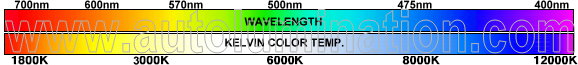
Led Kelvin Color Temperature
 LEDs come in all shapes and sizes, but the 3mm T-1 or 5mm T-1¾ are the most common.
The die is a small cube of semiconductor. The composition of the die determines the color of the light given off. The die sits in the top of the die cup, which is a reflector to reflect the light emitted by the die. The beam angle is determined by the shape of this relector. The epoxy body also is shaped to acts to effect the focus and appearance of the the light beam. The distance from the die cup to the domed end of the lens determines how tightly focused is the resulting beam of light. Some LEDs have flat, opaque, or even concave ends to help disperse the light into a wide beam.
LED Color
Visible LEDs

|
Wavelength nm |
Color Name |
Color Sample |
|---|---|---|
| over 1100 | Infrared | |
| 770-1100 | Longwave NIR | |
| 770-700 | Shortwave NIR | |
| 700-640 | Red | |
| 640-625 | Orange-Red | |
| 625-615 | Orange | |
| 615-600 | Amber | |
| 600-585 | Yellow | |
| 585-555 | Yellow-Green | |
| 555-520 | Green | |
| 520-480 | Blue-Green | |
| 480-450 | Blue | |
| 450-430 | Indigo | |
| 430-395 | Violet | |
| 395-320 | UV-A | |
| 320-280 | UV-B | |
| 280-100 | UV-C |
LED colors are often specified in "nm", or nanometers, which is the wavelength of the light. The wavelength given is the wavelength at peak output. LEDs are not perfectly monochromatic, but rather produce a range of wavelengths over a small region of the spectrum. The graph on the left shows color vs. intensity for a typical green LED. Notice the peak is at about 565 nm, but it is actually emitting light over a range of about 520 nm to 610 nm. Spectral line half-width is the width of this curve at 50% intensity (0.5 on the Y-axis). For this LED, it is about 30 nm. Spectral line half-width is a measure of how "pure" (monochromatic) the color is.
Notice the temperature (Ta) given in the upper right corner of the graph. LEDs emit slightly different colors at different temperatures. They also emit different colors at different currents, especially white LEDs which depend on phosphors to change the colored light of the die to white light.
This is why white leds (in particular) will never match perfectly in color.
Infrared LEDs
The infrared band can be divided into Near Infrared (NIR) and Far Infrared (IR). Far infrared is the thermal infrared used to detect hot objects or see heat leaks in buildings, and is way beyond the range of LEDs. (NIR can be further divided into two bands, longwave and shortwave NIR, based on how film and CCD cameras react.
Infrared LEDs are sometimes called IREDs (Infra Red Emitting Diodes).
Ultraviolet LEDs
Ultraviolet light is divided into three bands: UV-A, which is fairly innocuous; UV-B, which causes sunburns; and UV-C, which kills things. Most UV-B and all UV-C from the sun is filtered out by the ozone layer, so we get very little of it naturally. LEDs emit UV-A.
400 nm is a pretty common wavelength for UV LEDs. This is right on the border between the violet and ultraviolet, so a significant portion of the light emitted is visible. For this reason 400 nm UV LEDs are sometimes rated in millicandela, even though as much as half of their energy is invisible. LEDs with lower wavelengths, such as 380nm, are usually not rated in millicandela, but in milliwatts.
YOU SHOULD NOT STARE INTO ANY LED DUE TO ITS BRIGHTNESS. MOST LEDS WILL INVOKE PAIN TO THE EYE TO WARN YOU TO LOOK AWAY. ULTRAVIOLET LEDS ARE PARTICULARLY DANGEROUS, BECAUSE A LARGE PORTION OF THE RADIATION EMITTED IS IN THE VISIBLE RANGE. THE RESULT IS THAT YOUR EYES WILL NOT INVOKE PAIN TO WARN YOU THAT THEY ARE HARMING YOUR EYES.
White light is a mixture of all the colors. Color "Temperature" is a misnomer and is not understood by most people. This is not helped by all the false advertising and hype that is used by marketers to sell their products. Color "Temperature" is a measure of the relative amounts of red or blue light being emitted. It is not a measure of temperature at all.
Higher color temperatures have more blue. A higher color temperature, is not necessarily an indication of a higher quality, or more expensive light. It is not a brighter light. If you want super high color temperature, just buy a blue light. It is has infinite color temperature which is higher than any "super or hyper" white light.
Kelvin Color Scale
|
|
|
Color Temperature |
Common Example |
|---|---|
| 2000° | Gaslight |
| 2470° | 15 watt incandescent bulb |
| 2565° | 60 watt incandescent bulb |
| 2665° | 100 watt incandescent bulb |
| 2755° | 500 watt incandescent bulb |
| 2900° | 500 watt Krypton bulb |
| 3100° | Projector type filament bulb |
| 3250° | Photo Flood |
| 3400° | Halogen |
| 3900° | Carbon arc |
| 4200° | Moonlight |
| 4700° | Industrial smog |
| 5100° | Hazy weather |
| 5500° | Sun 30° above horizon |
| 6100° | Sun 50° above horizon |
| 6700° | Electronic Flash |
| 7400° | Overcast sky |
| 8300° | Foggy weather |
| 30,000° | Blue sky |
Remember that this is a measure of color, not brightness, so don't freak out because moonlight is "hotter" than a carbon arc! It just means that the color is bluer, that's all.
White and blue LEDs have a color temperature, but leds not in the white-blue spectrum do not.
LED Brightness
The total power consumed by a light is measured in watts. How bright the object appears, however, will depend on two additional factors:
- how much radiant flux is emitted toward the observer; and
- how sensitive the observer is to the wavelength(s) of the light.
To quantify the first, the steradian, a solid (3-D) sphere is used.
If the radiant flux of a source is radiated uniformly in all directions, the radiant intensity will be simply the total radiant flux divided by 12.57 (4π) steradians, the solid angle of a complete sphere. In the case of LEDs, the radiant flux is usually concentrated into a beam, however, so the radiant intensity will be the radiant flux divided by the solid angle of the beam. Beam angles are usually expressed in degrees, while radiant intensity is usually expressed in mW/sr, making a conversion from beam angle to steradians necessary:
sr = 2 π (1 - cos(θ/2))
where sr is the solid angle in steradians, and θ is the beam angle.
Luminous flux and luminous intensity are measurements like radiant power and radiant intensity, only adjusted for the sensitivity of the human eye. Radiant power of a wavelength of 555 nm is multiplied by a factor of 1, but light of higher and lower wavelengths are multiplied by lower factors, until infrared and ultraviolet wavelengths are reached, when the radiant power is multiplied by zero.
Luminous flux is measured in lumen, while luminous intensity is measured in lumen per steradian, also called a candela.
The relationship between luminous flux, luminous intensity, and beam angle means is that focusing a given LED into a tighter beam (decreasing the beam angle) will increase its luminous intensity (brightness) without actually increasing the luminous flux (amount of light) it puts out. Keep this in mind when buying LEDs for illuminating purposes - a 2000 mcd 30° LED puts out just as much light as am 8000 mcd LED with a 15° viewing angle. (The angle is half in both width and height, so the beam is four times as bright.) This is one of the reasons that ultra-bright LEDs are often "water clear", to keep the light going in one direction and not diffuse it all over the place.
The brightness of LEDs is measured in millicandela (mcd), or thousandths of a candela. Indicator LEDs are typically in the 50 mcd range; "ultra-bright" LEDs can reach 15,000 mcd, or higher (the 617 nm Luxeon Star (part number LXHL-NH94) can reach 825,000 mcd), but the cost is these leds makes them not yet practical for common use.
By way of comparison, a typical 100 watt incandescent bulb puts out around 1700 lumen - if that light is radiated equally in all directions, it will have a brightness of around 135,000 mcd. Focused into a 20° beam, it will have a brightness of around 18,000,000 mcd.
38-11 Illumination
I ntensity of light and other electromagnetic radiation as power per unit area, measured in watts per square meter. Similarly, the total rate of radiation of energy from any of the sources of light discussed in Sec. 38-2 is called the radiant power or radiant flux, measured in watts. These quantities are not adequate to measure the visual sensation of brightness, however, for two reasons: First, not all the radiation from a source lies in the visible spectrum; and ordinary incandescent light bulb radiates more energy in the infrared than in the visible spectrum. Second, the eye is not equally sensitive to all wavelengths; a bulb emitting 1 watt of yellow light appears brighter than one emitting one watt of blue light.
The quantity analogous to radiant power, but compensated to include the above effects, is called luminous flux denoted by F. The unit of luminous flux is the lumen, abbreviated lm, defined as that quantity of light emitted by 1/60 cm² surface area of pure platinum at its melting temperature (about 1770°C), within a solid angle of 1 steradian (1 sr). As an example, the total light output (luminous flux) of a 40-watt incandescent light bulb is about 500 lm, while that of a 40-watt fluorescent tube is about 2300 lm.
When luminous flux strikes a surface, the surface is said to be illuminated. The intensity of illumination, analogous to the intensity of electromagnetic radiation (which is power per unit area) is the luminous flux per unit area, called the illuminance, denoted by E. The unit of illuminance is the lumen per square meter, also called the lux:
1 lux = 1 lm/m²
An older unit, the lumen per square foot, or foot-candle, has become obsolete. If luminous flux F falls at a normal incidence on an area A, the illuminance E is given by
E = F ÷ A
Most light sources do not radiate equally in all directions; it is useful to have a quantity that describes the intensity of a source in a specific direction, without using any specific distance from the source. We place the source at the center of an imaginary sphere of radius R. A small area A of the sphere subtends a solid angle [omega] given by [omega]=A÷R². If the luminous flux passing through this area is F, we define the luminous intensity I in the direction of the area as
I = F ÷ [omega]
The unit of luminous intensity is one lumen per steradian, also called one candela, abbreviated cd:
1 cd = 1 lm/sr
The term "luminous intensity" is somewhat misleading. The usual usage of intensity connotes power per unit area, and the intensity of radiation from a point source decreases as the square of distance. Luminous intensity, however, is flux per unit solid angle, not per unit area, and the luminous intensity of a source in a particular direction does not decrease with increasing distance.
EXAMPLE: A certain 100-watt bulb emits a total luminous flux of 1200 lm, distributed uniformly over a hemisphere. Find the illuminance and the luminous intensity at a distance of 1 m, and at 5 m.
SOLUTION: The area of a half-sphere of radius 1 m is
(2[pi])(1 m)² = 6.28 m²
The illuminance at 1 m is
E = 1200 lm ÷ 6.28 m² = 191 lm/m² = 191 lux
Similarly the illuminance at 5 m is
E = 1200 lm ÷ 157 m² = 7.64 lm/m² = 7.64 lux
This is smaller by a factor of 5² than the illuminance at 1 m, and illustrates the inverse-square law for illuminance from a point source.
The solid angle subtended by a hemisphere is 2[pi] sr. The luminous intensity is
I = 1200 lm ÷ 2[pi] sr = 191 lm/sr = 191 cd.
The luminous intensity does not depend on distance.
LED Brightness - IR and UV LEDs
Question: How bright is an IR LED?
Answer: 0 mcd.
Since candela and lumen are units that are adjusted to compensate for the varying sensitivity of the human eye to different wavelengths, and IR and UV are totally invisible (by definition) to the human eye, all IR and UV LEDs are automatically zero lumens and zero mcd. These units of measure, used for visible-light LEDs, can't be used for UV and IR LEDs (despite the "3000 mcd IR LED" currently on eBay).
IR and UV LEDs are measured in watts for radiant flux and watts/steradian for radiant intensity. A fairly typical "bright" IR LED will put out about 27 mW/sr, though they go up to 250 mW/sr or so. Signaling LEDs, like for TV remotes, are considerably less powerful.
HOWEVER - keep in mind that LEDs are not perfectly monochromatic. If their peak output is close to the visible spectrum, then their bandwidth may overlap the visible spectrum enough to be visible as a dim cherry-red light. Furthermore, some people can see further into the red region than can others, seeing as deep-red colors that to others are invisible infrared. While it would be possible to give such an LED a rating in millicandella, it would be misleading.
This dim red glow, by the way, is often claimed - wrongly - to differentiate good illumination IR LEDs from much dimmer IR LEDs. Which LED is better for such a purpose is totally dependant on the wavelength at which the receiver is most sensitive.
Using LEDs
 As a rule of thumb, different color LEDs require different forward voltages to operate - red LEDs take the least, and as the color moves up the color spectrum toward blue, the voltage requirement increases. Typically, a red LED requires about 2 volts, while blue LEDs require around 4 volts. Typical LEDs, however, require 20 to 30 mA of current, regardless of their voltage requirements. The table on the left shows how much current a typical red LED will draw at various voltages.
Notice that this LED draws no current under 1.7 volts; the LED is "off". Between 1.7 volts and about 1.95 volts, the "dynamic resistance", the ratio of voltage to current, decreases to 4 ohms. Above 1.95 volts, the LED is fully "on", and dynamic resistance remains constant. Dynamic resistance differs from resistance in that the curve isn't linear. Just remember that this non-linear relationship between voltage and current means that Ohm's Law doesn't work for LEDs.
Notice how steep the slope is - almost vertical. LEDs have a much more vertical slope than do normal diodes (but not as bad as laser diodes).This means that a tiny increase in voltage can produce a large increase current, and lots of smoke. In the above-mentioned LED, 2 volts is required to drive the LED properly, but as little as 2.04 volts could destroy it. To keep the current down to a reasonable level, a series resistor must be included in the circuit.
The formula for calculating the value of the series resistor is:
Rseries = (V - Vf) / If
where Rseries is the resistor value in ohms, V is the supply voltage, Vf is the voltage drop across the LED, and If is the current the LED should see.
 For example, the above LED would run very nicely off 12 volts with a 500 ohm series resistor. Since 500 ohms is an odd value, you could do almost as well with a 470 ohm resistor, which would let the LED draw 21 mA.
You can use a single resistor to control the current to a series of LEDs, in which case Vf is the total voltage drop across all the LEDs. You can sometimes get away with using a single resistor to control the current to a group of LEDs in parallel, but it's not generally a good idea - if there is any variation in the LEDs, they won't each draw the same current, resulting in differences in brightness - or in smoke.
Driving LEDs with AC
There are several factors to consider. One is that the LED will only conduct during that portion of the positive half of the cycle during which the voltage is above the threshold voltage of the LED. This means that the LED is conducting less than half the time, which will effect brightness.
Second, even when the LED is conducting, the average voltage will be far less than the peak voltage. The average voltage of the positive half of a sine wave is only 64% of the peak voltage. (Think "area under the curve.") Brightness is therefore further reduced.
 This is what I mean. The X axis is time, the Y axis is voltage. The blue line is the supply voltage; the red line is the LED threshold. In this case, the peak voltage is 5 volts, and the threshold is 1.2 volts (typical for a red LED). The "effective voltage" (my term), is the voltage that is above the threshold voltage, the voltage that actually lights the LED; the rest of the voltage does nothing, either because it is under the threshold, or it's of the wrong polarity. Effective voltage is shown in the graph by the gray areas. The light gray area is the average effective voltage for
an AC supply voltage; here, 1.04 volts. The dark gray area is the average effective voltage for a DC supply, 3.8 volts, that the AC supply voltage misses. The light gray area is a mere 27% of the area of both gray areas combined. If the LED had a threshold voltage of zero (wouldn't that be nice?) the effective AC voltage would still be only 32% of the effective DC voltage. As threshold voltage rises, the "duty cycle" goes down from there.
This is what I mean. The X axis is time, the Y axis is voltage. The blue line is the supply voltage; the red line is the LED threshold. In this case, the peak voltage is 5 volts, and the threshold is 1.2 volts (typical for a red LED). The "effective voltage" (my term), is the voltage that is above the threshold voltage, the voltage that actually lights the LED; the rest of the voltage does nothing, either because it is under the threshold, or it's of the wrong polarity. Effective voltage is shown in the graph by the gray areas. The light gray area is the average effective voltage for
an AC supply voltage; here, 1.04 volts. The dark gray area is the average effective voltage for a DC supply, 3.8 volts, that the AC supply voltage misses. The light gray area is a mere 27% of the area of both gray areas combined. If the LED had a threshold voltage of zero (wouldn't that be nice?) the effective AC voltage would still be only 32% of the effective DC voltage. As threshold voltage rises, the "duty cycle" goes down from there.
The effective voltage is the (V-Vt) term from the formula given above, and can replace it for calculating the value of the desired resistor.
You could increase the effective AC voltage toward the theoretical maximum of 32% of the effective DC voltage by increasing the supply voltage - this makes the threshold voltage a smaller portion of the peak voltage, so the LED turns on sooner in the cycle and stays on longer. But you have to avoid using a peak voltage greater than the reverse voltage that the LED can tolerate - typically only 5 volts. Remember that when the LED isn't conducting, all the voltage drop will be across the LED. You can sidestep this problem by including a separate diode - silicon diodes can withstand far more reverse voltage than LEDs can, although an additional diode will impose a second threshold voltage. Incorporating a full-wave bridge rectifier would let you drive the LED with both halves of the cycle, increasing the maximum possible effective voltage to 64% of that of DC, at the price of two additional threshold voltages.
Some white LEDs require forward voltages (typically 3.5 or 4 volts) very close to their maximum reverse voltage (typically 5 volts), so the LED will only be on for a very small fraction of the cycle, making it very dim. For example, an LED requiring 3.5 volts driven on 5 volts AC would only an effective AC voltage of only 0.25 volts, only 17% of the effective DC voltage of 1.5 volts.
To compensate for the low average effective voltage, we'd want to drive the LED pretty hard to get the average current up to 20 mA. If the effective voltage is only 0.25 volts, then the resistor should be 13 ohms, and the peak current will be 120 mA. Can the LED stand a peak of 120 mA? Probably not.
One possible solution is two LEDs in reverse-parallel, that is, one polarized to light during the positive half of the cycle, and the other polarized to light during the negative half. Right off the bat, this doubles the light output, since we're now using both halves"" alt align="right" width="234" height="207">f the cycle. Furthermore, since the only reverse voltage each LED will see is the forward voltage drop of the other LED, you can drive them with just about any voltage you want, so the "duty cycle" can approach 64% pretty closely. Using square-wave AC instead of sine-wave AC would let you reach almost 100%, either by using two reverse-parallel LEDs, or using one LED driven at twice the normal current for half the cycle.
|
|